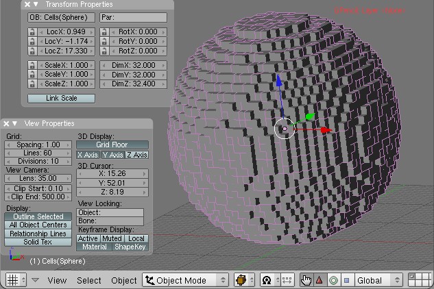
You may remember the “Legoizer” script I’ve been working on for Blender. It uses an existing script and one I’ve created to generate “layers” of LEGO patterns for building.
I got a lot of great suggestions on my last entry for how to automate the process of taking a screenshot, but sadly when it came down to implementing them things didn’t go so well. Luckily Angelo from Abandon Hope Games was kind enough to take the time to help me get the environmentals in Blender set up just right for rendering a “pattern slice.”
Step 0: Start with an object made of objects
The AddCells script uses DupliVerts to create an object made of references to another object. We’ll get to that in a minute, but first, let’s assume you have an object:
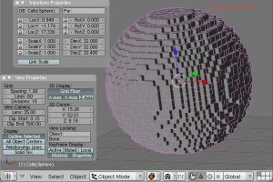
Step 1: Set up the camera
We want the camera to be facing down and rendering orthographic(all lines parallel) rather than perspective.
Make sure you’re in Object Mode and select the camera.
Press Alt+G and then Alt+R (confirming the dialogs) to return it to the origin.
Hit F9 to get into the Editing panel
Click the button labeled Orthographic in the Camera tab
Press 1 on your number pad to get a side view of the scene. Click the blue transform handle of your camera and move it up along the Z axis so it is well above your object.
Press 0 on your number pad and you should see a rectangular bounding box around your object (or perhaps around nothing) which represents the are which the camera sees.
Scroll the “lens” option right above the Orthographic button to zoom in/out so your
If you do a test render now with F12, you’ll probably see a badly lit (perhaps almost all black) render of your object from the top down.
Select the existing light in your scene and press x on your keyboard to delete it.
Press space bar to bring up a dialog, and go to Add > Lamp > Sun
It doesn’t matter where the lamp is, as long as it’s facing down (which it is by default).
Step 3: Configure your materials
I mentioned earlier that our object was made up of DupliVerts.
These aren’t “real” objects, which is why I had such trouble applying materials to them. You need to apply the material to the reference object, which is generally somewhere in the middle of it. I usually do this by switching to the Outliner menu and finding the source cube manually.
![]() Once we have our source object selected, hit F5 to bring up the Shading panel and click Add New under Links and Pipeline.
Once we have our source object selected, hit F5 to bring up the Shading panel and click Add New under Links and Pipeline.
Pick a new color for your object. This will be the color of the lines in your final rendered image, so pick something that contrasts with your background color (which defaults to blue).
Click the Wire button under Links and Pipeline
 Your object in the viewport should take on the color you’ve selected. If if doesn’t, you probably didn’t select the correct source object.
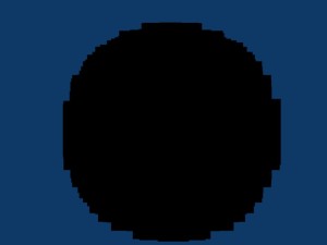
Hit F12 to render. Viola!
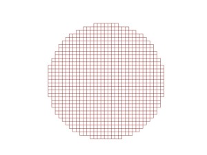 Now that we have our environment set up the way we want, rendering via script is easy. I’ve updated the script source (now on gist) to call Render when it’s done slicing and save the file to my hard drive.
This all works great, but of course there’s a new problem. Since we want to iterate over the entire object, I need to “reset” it back to being whole again. While I’ve saved an undo point I don’t think you can call that point via the API. In the current iteration of the script I save the vectors of each vertex before deleting it and then call verts.extend to add them back. This works great except…
The vectors for the verticies are transformed to be in the selected object’s local space, which is necessary for “layer 1” to be the first layer of the object and so forth. Unfortunately I haven’t yet figured out how to transform those verticies back. So when I run the script it dutifully reassembles my sphere originating from the center of the object. So there’s still some work to be done there.
